





 Volume: 74, Issue: 6, June 2026
 Qingfan Zeng
Analysis and Design of Dual-Injection Injection-Locked Frequency Triplers With Wide Locking Range and High Harmonic Rejection
Abstract
DOI: 10.1109/TMTT.2026.3678612
IEEEXplore: https://ieeexplore.ieee.org/document/11475889
Device
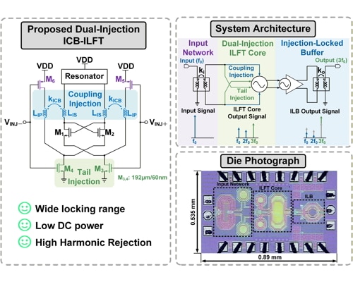
A dual-injection injection-locked frequency tripler (ILFT) with wide locking range (LR), low power consumption and high harmonic rejection ratio (HRR) fabricated in 65-nm CMOS.
Spectrum
17.4 – 26.4 GHz output signal
Novelty
The dual-injection ILFT consists of a tail injection path and a coupling injection path. The tail injection path leverages a hard-switching behavior to reshape the injection current into a pseudo-square waveform, which enhances the strength of the third harmonic to extend the locking range.
The coupling injection path utilizes both electric and magnetic coupling of the injection-current-boosting (ICB) transformer to further enhance the injection current.
By combining the two injection paths, the third harmonic currents are combined in phase, while the other undesired harmonics are suppressed out of phase. An injection-locked buffer (ILB) is cascaded to improve the flatness of the output power while further suppressing undesirable harmonics.
Application
millimeter-wave communication systems for portable applications.
Performance
-9.1 dBm output power; 41% locking range from 17.4 to 26.4 GHz; >40 dBc HRR from 17.4 to 24 GHz.
3.2 mW (core) power consumption; 14.9 mW total power consumption; 0.48 mm2 chip area.